nPControl Nanopositioner Software
Nanopositioner control is made easy with nPoint’s Windows-based software, nPControl. Graphical controls facilitate easy adjustment of control parameters, step-response verification, and enabling of advanced control modes.
nPoint systems are also compatible with the following software environments:
- LabVIEW and DLL drivers
- EPICS Drivers
- uManager Drivers
- Nikon Elements Compatible
- ScanImage Compatible
1. Control Loop Tuning
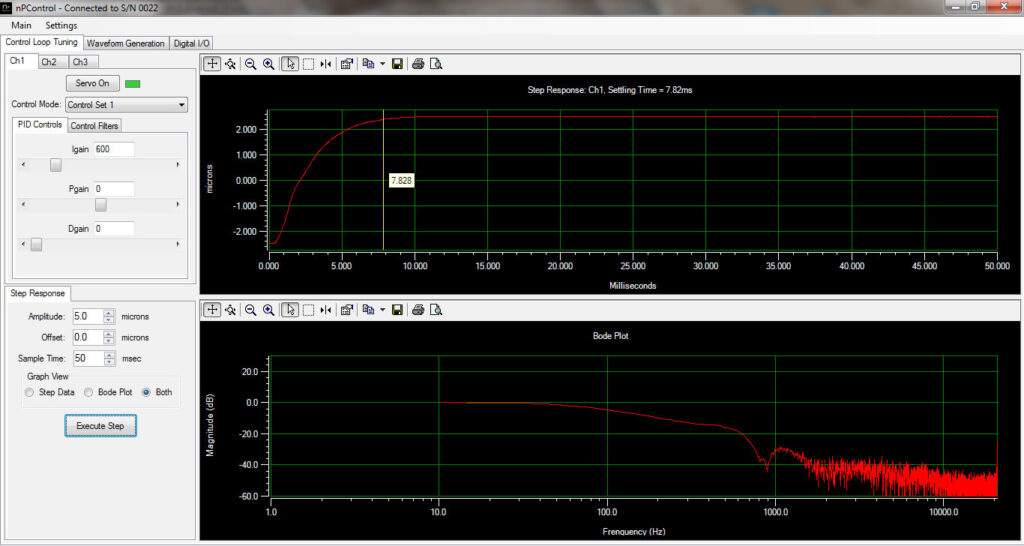
The Control Loop Tuning window allows the response of a nanopositioning system to be optimized for various applications via adjustable control parameters. This may be necessary when external factors, such as load, change the dynamic characteristics of the nanopositioning system. The user can adjust the PID gains to achieve the desired step response.
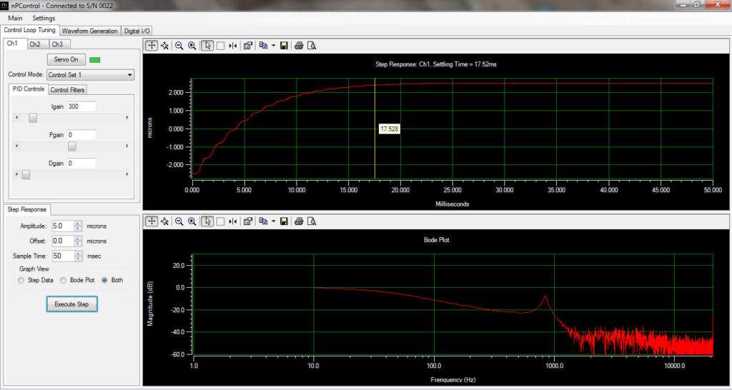
The user can command one axis (channel) while simultaneously monitoring additional axes. Up to four different control modes can be programmed per channel. Each control mode can store up to two notch filters and a 2nd integrator.
The use of notch filters allow for higher PID gains to be used while keeping the system stable. The use of higher PID gains result in a faster step response.
Nanopositioning applications involving scanning benefit greatly from the use of the 2nd integrator. The tracking error can be minimized as shown at right.
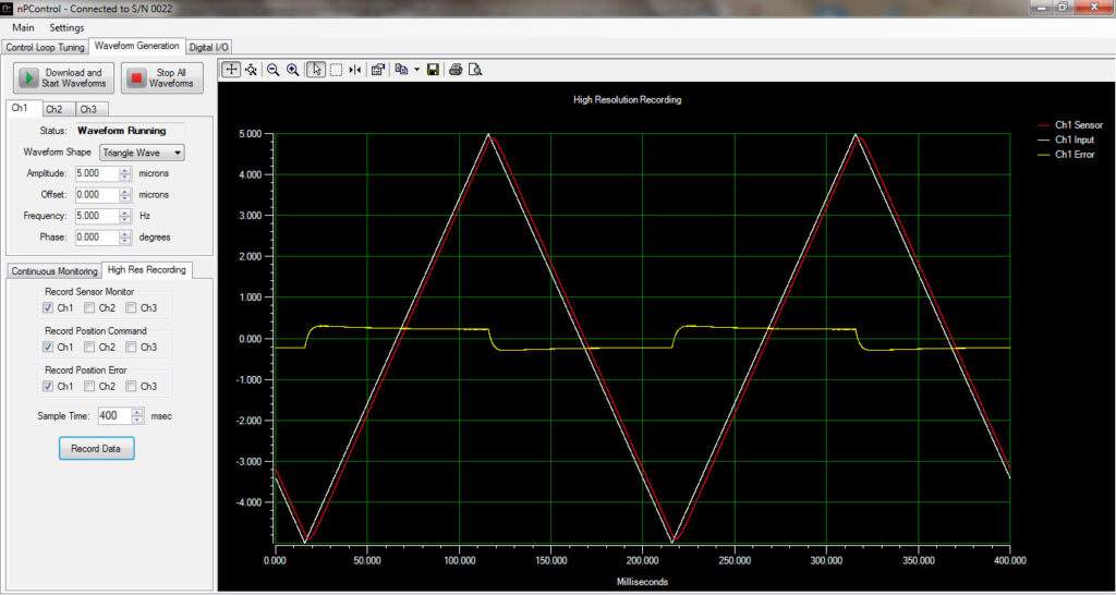
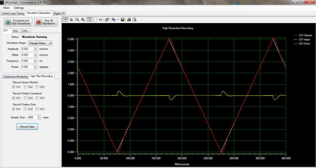
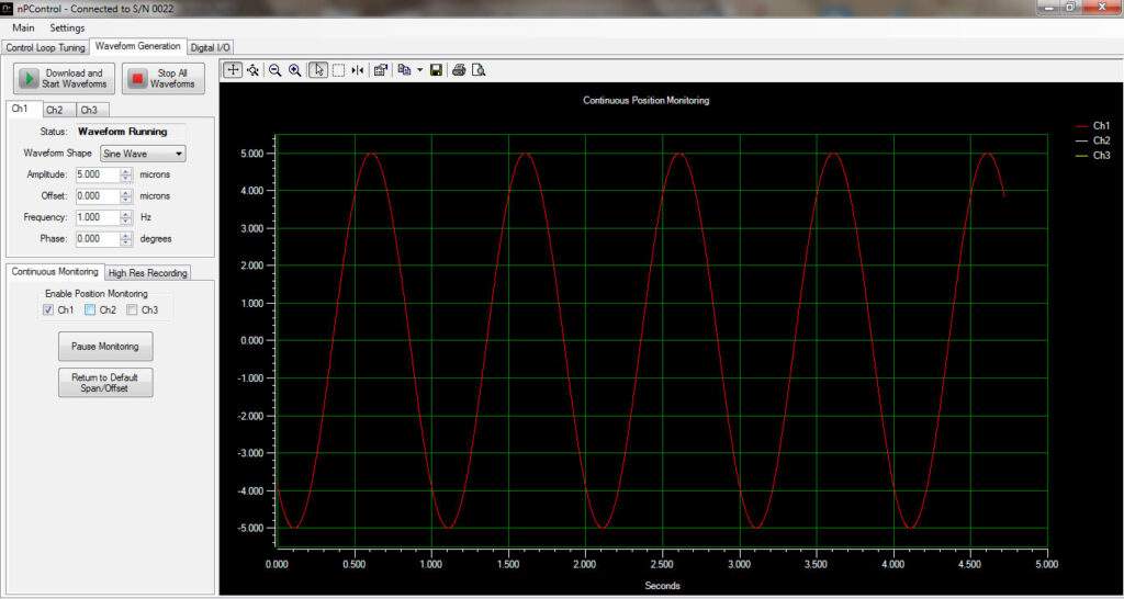
2. Waveform Generation
nPoint LC.400 and C.400 nanopositioner controllers are equipped with a Digital Waveform Generator. The Waveform Generation can be used to generate periodic motion on any stage axis. Different periodic waveforms can be selected for each channel. User-defined waveforms can also be uploaded.
The High Res Recording tab allows the user to record up to two seconds of high resolution data. The commanded position, the actual position and the position error for any channel can be recorded simultaneously. Two seconds of data is equivalent to 83333 data points. This allows the user to better understand how the control parameters affect position tracking errors, axes cross-talk, etc.
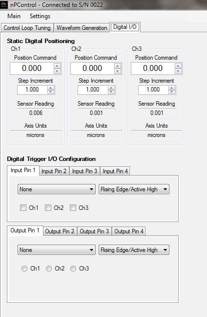
3. Digital I/O
The position of a piezo stage can be set using the Digital I/O interface. The sensor reading is continuously monitored. The 400 series controllers are equipped with programmable digital I/O capabilities through the 9-pin D-sub connector located on the back (LC.400 series) or the front (C.400 series) panel. Up to four input and four output trigger configurations can be programmed.
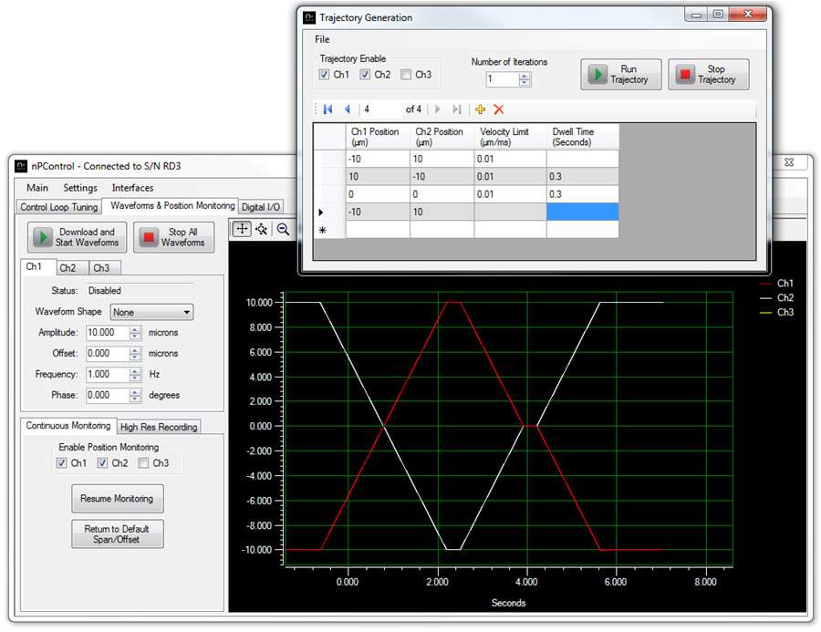
4. Trajectory Generation
The Trajectory Generation Interface allows up to 500 position coordinates to be defined with velocity and dwell time specified individually for each move.
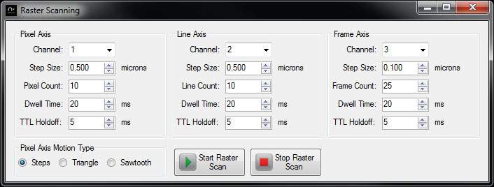
5. Raster Scanning
The Raster Scanning Interface allows the user to define a raster pattern with up to three axes. TTL signals can be used for data-acquisition synchronization.