There are many factors to consider when looking for nanopositioning piezo stages. This blogpost focuses on flexure-based piezo electric stages and will highlight some items that are important when evaluating different stages and systems.
The advantages of such a system include:
- Frictionless motion
- High stiffness
- High-speed motion
- Small parasitic errors
One disadvantage of piezo stages is their limited range of motion. While some designs have the travel of up to 2mm most stages typically move a few hundred microns.
1. Travel Range
Travel range is the maximum distance a stage can move in a single axis. One of the most important things to note when considering the travel range is the tradeoff between that and specifications such as position noise and scanning speed The position noise of a stage will often increase with a larger travel distance while the scanning speed capability may decrease. While stages are designed for different purposes, as a rule of thumb when speed and resolution are important it is best to choose a stage with shorter travel ranges.
2. Axes of Motion
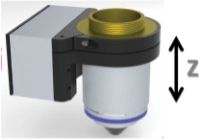
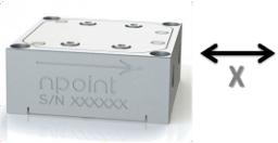
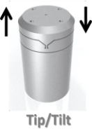
It is important to consider how many axes of motion are required for your application. Take a look at what planes of movement are most important. Nanopositioning systems have X, Z, XY, XYZ, and tip/tilt motion associated. Also consider the travel range necessary for each axis of movement.
Some examples can be seen below.
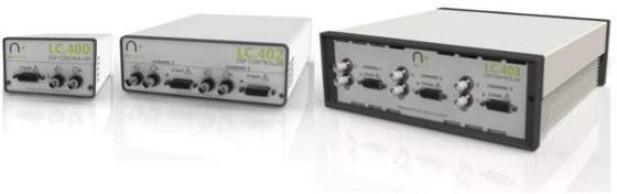
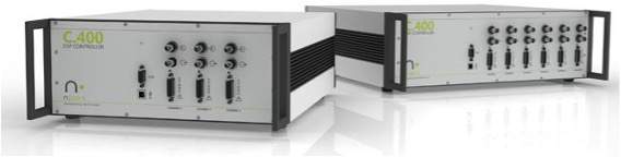
3. Controller
When choosing the controller that best fits your needs, first consider the number of axes that the stage will have. A controller must be selected with an equal amount of channels-to-axes of the stage. An XYZ stage would require a 3-channel controller. Each channel of the controller is used to communicate the necessary details to one axis of the stage. Controllers are available with up to six channels.
A controller is necessary for closed-loop control. It provides the drive signal to the piezo every 24 microseconds while at the same time analyzes the sensor-reported position data to ensure the stage is moving to the commanded position. A piezo driver can be used for applications where open-loop operation is adequate. Open-loop drive can be used for applications where the user “closes the loop” with additional electronics or in applications where accuracy and hysteresis are not an issue. Piezos exhibit creep and hysteresis so the resulting position could be off by 10% or more from the commanded position without closed-loop control.
PC software can be used along with the DSP controller to get the most out of a nanopositioning system.PID controls along with advanced control software allow a reduction in settling time with a load necessary to the application.
4. System Interface
There are multiple ways in which to communicate with a controller. The simplest way to command a stage to reach and maintain a position or to scan is by using the BNC analog inputs of the controller. Each channel is equipped with analog control and sensor monitor BNC connectors. A voltage range of -10V to 10V ensures that the maximum travel distance is used. Stages can also be calibrated for other input ranges as well.
The system can also be interfaced via Ethernet, USB, Digital I/O, or Step&Direction. The nPoint USB interface uses FTDI drivers compatible with many programming languages. The user can perform a variety of functions via the USB interface such as commanding position, reading the actual position (sensor signal) and changing control parameters when required. The digital I/O can assign different triggering functions to the 9-pin interface through the front panel software. The Step&Direction interface allows for easy integration of the piezo controller in highly automated industrial environments.
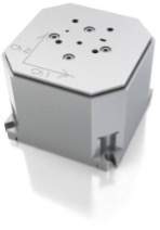
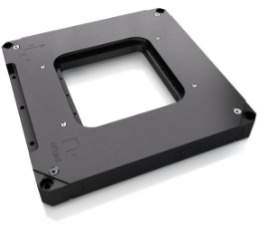
5. Stage Footprint/Aperture
The size and shape of a stage often determine its performance. Some stages are designed for certain functions like moving a microscope objective while others are designed solely for fast scanning applications. As a rule of thumb, if two stages offer the same scanning range and one is considerably larger than the other, the larger stage will have a higher resonance and be able to scan faster. Be sure to look at the physical size of the stage to determine if it will fit within the design requirements of your space. If an aperture is required make sure that the aperture is large enough to best fit your requirements.
1. Position Noise
Position noise is the amplitude of the stage movement when it is trying to maintain a position at a certain control-loop bandwidth. The control-loop bandwidth highly depends on the control settings. A common bandwidth value that nPoint uses to measure the noise is approximately one-tenth the resonant frequency of the stage. This measure is commonly used to define the resolution of nanopositioners and it is typically dominated by the sensor noise. If you interface with the nPoint controllers via the analog input you need to make sure that your voltage command is not noisy so that you maintain the high resolution (low noise) capability of the nPoint nanopositioning systems.
2. Settling Time
Settling time is the time it takes for a stage to move to a commanded position and settle to within 2% of the step size. A small signal step response reflects the dynamic characteristics of the system in greater detail. The time it takes to step 1 micrometer is a common measure used. It is important to note the difference between rise time and settling time. Rise time is the time it takes for the nanopositioning system to move from 10% of the commanded position to 90%. This time is often much quicker than settling time and, while it does depend on the relative speed at which a stage can step, it does not take into account the time it takes to for the stage to “settle” in the desired position. When a large step is used, i.e equal to the full travel range of the stage, then the settling time is most commonly limited by the current output capability of the controller.
3. Sensor
A position sensor is necessary to provide closed-loop control for the nanopositioning system. There are different types of sensors that can be used to provide the feedback required to eliminate non-linearity and hysteresis. Two common types of sensors are capacitive and strain gauge. Each has advantages for certain applications. Capacitive sensors provide the highest accuracy and resolution. Strain gauges are often used in lower-cost applications where resolution may not be as critical.
4. Resonant Frequency
The first (or lowest) resonant frequency per axis is typically specified for a nanopositioner. The resonant frequency could be of the mode along the motion axis or along other axes including rotation and other complex modes. In general, the higher the resonant frequency of a system, the higher the stability and working bandwidth the system will have. The resonant frequency of a stage is reduced when load on the stage is increased. When selecting a nanopositioner to move large samples it is important to understand how the resonant frequency will change when the nanopositioner is loaded.
5. Stage Operating Conditions
It is important to consider the conditions under which your nanopositioning system will be operating. Piezo stages can be made from various materials such as invar, stainless steel, titanium and aluminum. Piezo stages can operate in UHV and environments that require non-magnetic positioning. Custom stages can be designed for unique applications and choosing stage material is an important part of the process.