Piezo stages are often used to perform raster scans in alignment set-ups aimed at finding optical power peaks. Flexure-based piezo stages have the advantage of frictionless scanning which enables higher scanning speeds without wear.
The nPoint LC.400 controllers and GUI offer a variety of capabilities aimed at reducing the time that it is required to identify an optical peak. Central to this is the capability of the nPoint controllers to synchronously record 8 signals as often as every 24us. One or more of those signals can be an external signal of interest (like optical power). These signals are typically connected to one of the analog input BNC’s of the controller.
To demonstrate some of the current capabilities and on-going developments we present data using a XY 100um stage and an LC.402 controller. The XY100 stage caries an optical fiber that is scanned in front of a stationary optical fiber. A peak is present when the two fibers are aligned. The optical detector outputs voltage that is fed into one of the analog input BNC’s of the LC.402. The optical power is recorded in the controller as a function of the stage position.
A. Standard Spiral Scan
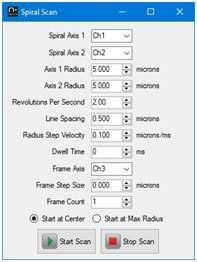
One can locate the peak by performing a spiral scan with high resolution. Spiral scans are preferred to raster scans because they do not induce as many mechanical vibrations. The user can define the spiral scan parameters in the nPControl GUI.
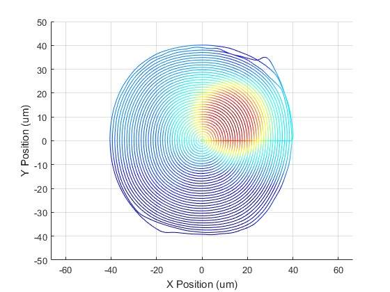
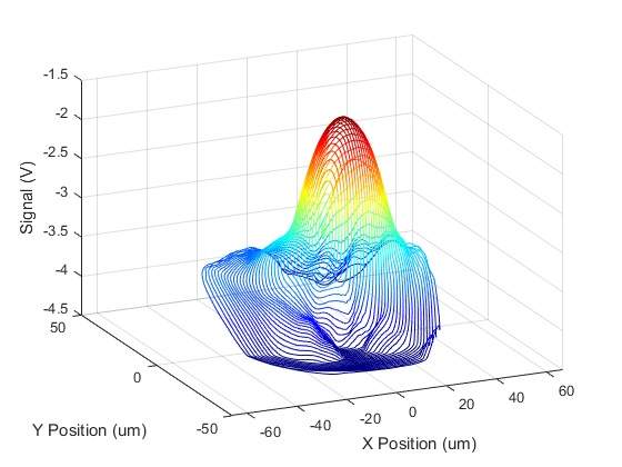
An 80 um spiral scan at 30 Hz is shown below. The line spacing of 1 um is adequate to accurately locate the peak. This scan took a little over 1.3 s to complete.
B. Smart Spiral Scan
An improvement to the Standard Spiral Scan is the Smart Spiral Scan. The nPoint GUI allows the user to program a coarse (larger area) and a fine (smaller area) spiral scan. The transition from the coarse scan to fine scan can be decided using different criteria, such as a threshold value. Once the signal of interest (in this case optical power) is above a specified value, the system will switch from the coarse spiral scan to the fine spiral scan. The fine spiral scan will use the threshold coordinates as its center. An offset can also be added to the center location of the fine scan.
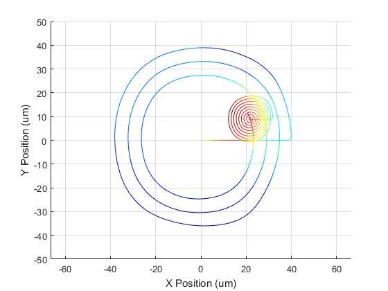
Data collected using the Smart Spiral Scan approach is shown below. The time to acquire the data was ~0.5 s.

Once the Standard or Smart Spiral scans are completed, the data is exported and the user can identify the location of the peak.
nPoint is currently developing peak-finding algorithms that can reside in the controller firmware so that the peak can be identified without exporting the data to a computer. This is aimed to further reduce amount of time required to complete an action by the user. One such method is detailed below.
C. Data-Guided Scan
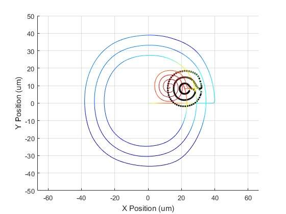
A smart spiral scan is initiated. As soon as the user-defined threshold value is identified the controller starts a Data-Guided scan that uses 3 concentric circles. During the Data Guided scan data is collected and analyzed to accurately identify the location of the optical power peak. The location of the peak does not necessarily have to lie on the path of the Data-Guide scan. The user controls parameters such as scanning speed and largest radius, as well as number of control-loop cycles between data points, the minimum being one control-loop cycle. The controller uses a least-squares regression to calculate the location of the peak. A fine spiral scan, centered at the peak location is performed to confirm that the location of the peak is accurate.
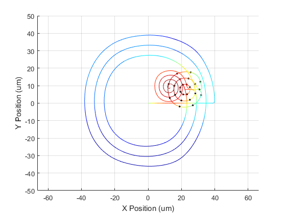
A Data-Guided scan that uses 50 data points per cycle (black dots) and 8 points per cycle are shown below. The peak is identified correctly in both cases as confirmed by the fine spiral scan that is centered at the peak location.
Using such method eliminates the need for data transfer from the nPoint controller to the computer, thus speeding up the peak-finding process. This type of algorithm can be adjusted by the user in an effort to speed-up the process.
Note that the methods described above can be used on any external signal recorded by the nPoint controller. nPoint works with a variety of OEM customers and customizes the firmware to better fit their integration requirements.