Finite element analysis (FEA) lets engineers explore the behavior of complex systems under real use conditions, running simulation after simulation to optimize overall performance by way of small design tweaks. The challenge is that FEA results are only as accurate as the simulation setup, as the saying goes, “garbage in equals garbage out.” One must also consider how complex to make the simulation and model. The more complex the simulation, the more accurate your results may be, but that complexity also increases the time to run the design (and the probability that your computer will crash mid-simulation!) Nuances like how you mesh your model, how you account for fasteners, and how you model non-rigid bodies all need to be considered and balanced. In some cases, fidelity is more important while in others, fast turnaround is a priority. Fine-tuning a simulation to meet project goals requires expertise, an intuitive understanding of the process, and a bag of tricks developed from experience. Let’s look at how the MOSO team used their bag of FEA tricks to speed the redesign of a medical device.
Effective simulations in action
Bringing a medical device to market is a lengthy and capital-intensive process. The design alone can take several years, especially when it involves precision motion. The return on that investment is a product that can remain on the market for a decade or more. Eventually, however, even the most advanced devices start to age out. At that point, manufacturers seek to broaden into new markets, either by reducing cost or refreshing the design. This kind of project provides a perfect example of how FEA can reduce redesign efforts.
A few years ago, a customer who builds surgical instrumentation approached our team with a challenge: How could they reduce our costs and expand their list of prospective customers? The original design was built for hospitals and surgical centers, which have double doors leading to operating rooms. To expand the list of available customers, the company wanted to expand to medical offices with only single-door access. They would need to maintain the stability and precision motion of the system while reducing its size and weight while reducing system size and weight so that it would be portable enough to fit through the door of a standard examining room.
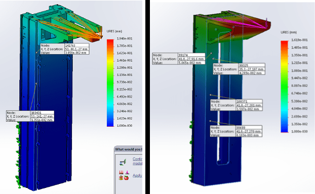
The first step was to build a model of the original design and run FEA simulations so that we could study it before making changes (see figure 1). The system included a main structural column supporting a cantilevered 2D positioning stage suspended over a patient. Once the surgeon moved the stage into position, the laser cutting system on the stage needed to remain dead still. The challenge for the Motion Solutions design team was to shrink the structural components and remove material to reduce both size and weight without compromising the stiffness or motion performance.

Figure 1: FEA results for the original design (left) and the revised design (right) show a 16.8% increase in column stiffness while achieving a 48.8% reduction in mass
Once our team had completed the preliminary analysis and fully understood the initial design, they could alter the model and use FEA to simulate the effects of changes. They began with relatively coarse meshes to rapidly iterate. As the results approached our design targets, the mesh could become finer, and additional details added to ensure the accuracy of the simulation results. Step by step, the design improved, iterating to achieve project goals.
Making the mesh better
The key in FEA is to develop a simulation that will closely mimic how the prototype and production systems will behave in operation. If the goal is to comprehensively simulate the performance of the finished design under real-world conditions, the mesh and model need to be more detailed, but the trade-off for the detail is longer run times for the computation. If the goal is just to check the effect of a minor change, then a mesh that is only high resolution around the modification may answer the question without taking a day for the computation to run.
A key design target in the aforementioned project was to reduce the weight of the structure while maintaining stiffness. FEA enabled our team to check the results, but only if the model and simulation adequately represented the system. Mass reducing a structural member can be tricky. Removing too much material can cause it to be overly compliant so that it deforms too much when loaded. If the simulation hadn’t accurately represented the system, it could lead to false results. Discovering at the prototype stage that the supposedly stiff platform deflects under load like a diving board is a nasty surprise that can lead to major delays in a program, as well as massive cost overruns.
Success comes from experience. Each time the Motion Solutions team models and builds a system, they’re able to compare the theoretical results with empirical data. Over hundreds of designs and years of experience, our design engineers have developed tips and techniques to optimize the mesh. Some of our best practices include:
- Modeling bearing blocks and drive-screw nuts as rigid placeholders, because CAD models don’t offer accurate enough representations for this analysis
- Modeling bearing-rail interfaces as stiff springs with approximate K values extrapolated from relevant load-deflection curves that act only in the radial direction, with zero resistance in the axial direction
- Modeling the interface between the drive nut and screw as an infinitely stiff spring, presenting resistance only in the axial direction
We’ve also fine-tuned the process itself, for example in the way we handle fasteners. Precision motion systems can incorporate hundreds of fasteners. While those fasteners introduce stresses in the system and are necessary for final simulations, they are difficult to add to initial simulations and can significantly increase computation time. A favored technique in our team is to complete the rest of the model and our preliminary FEA runs. Only at the very end, when the model is otherwise complete and we’re satisfied with the performance, will we add in the fasteners and make final system adjustments. This approach saves a substantial amount of time in the development process.
Conclusion
Building an appropriate simulation for each FEA iteration is essential to meeting final system design goals in an efficient manner. The experience and expertise of the Motion Solutions engineering team enabled us to meet all design objectives of the medical device redesign while remaining on schedule and at budget. The use of FEA to modify the system enabled the medical OEM to target new revenue streams while getting the product refresh to market quickly. Instead of the roughly three or four years normally required to design and release this sort of product, our work enabled the manufacturer to release the update in just 18 months.
Inaccurate FEA results from a poorly built simulation can result in an unacceptable prototype, sending you right back to the drawing board. That increases costs and adds weeks or months in terms of machining, procurement time, lead time, etc. Motion Solutions engineers have the experience and know the tricks to make sure our FEA results closely match how your prototype/production systems will actually behave. Find out how we can help you get a better product to market faster. Contact us at [email protected] or schedule a meeting with our team at https://calendly.com/casey-covey/meet.

About the Author
Casey Covey
Director of Sales, Motion Solutions
Casey is a degreed mechanical engineer with 15 years of experience in the motion control and automation industry.


