

Answering the big science questions of our time around molecular reactions, biological dynamics, and materials properties at an atomic scale takes powerful tools. When the Linac Coherent Light Source (LCLS) was first commissioned in 2009, this x-ray free-electron laser (XFEL) was the brightest, fastest, and highest energy x-ray laser of its time. In order to keep pace with the requirements of science, however, it requires a major upgrade. the LCLS-II promises to change our understanding of the world around us, opening the way for new technologies, new medical treatments, and new ways of interacting with our environment. And Motion Solutions is playing a key role by supplying undulators that are fundamental to the operation of the entire system.
X-ray science
One of the challenges of imaging atomic-scale features is that the wavelengths used need to be even smaller. The diameter of an iodine ion, for example, is about 4.4 Å (4.4 ´10-10 m). Capturing high-speed dynamics requires pulsed sources with pulse lengths shorter than the duration of the process. The types of dynamic studies discussed above require coherent sources capable of generating femtosecond (10-15 s) pulses with wavelengths just a few ångströms long. This type of output can only be generated by an XFEL.
In an XFEL, high-speed electrons produced by an accelerator travel in a vacuum tube that passes through a series of magnetic components known as undulators. These devices generate very strong, complex magnetic fields that force the electrons into sinusoidal trajectories. In response, the electrons emit x-ray radiation. Normally, this output is incoherent (random phase), but as the electron beam passes through a sequence of multiple undulators, the electrons collect into tight bunches. The result is a pulse train of monochromatic, coherent (in phase) x-ray output that can be used to capture ultra-high-resolution images. These million-pulse trains of femtosecond pulses can be used as strobes to image ultrafast molecular dynamics and biological processes.
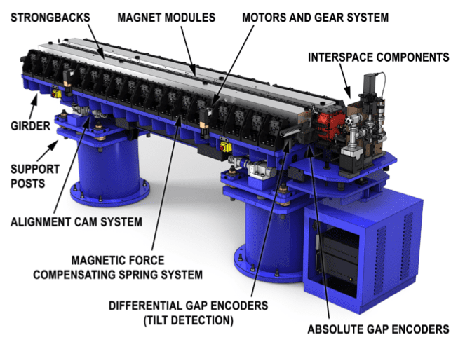
An undulator consists of a pair of parallel structural pieces known as strongbacks. They are lined with a series of magnet modules of alternating poles that generate the complex magnetic field distribution. The strongbacks need to be positioned to maintain a gap held constant to within micrometers across the length of the undulators. That task is particularly important because gap width controls the energies/wavelength of the x-rays generated. It’s also a nontrivial task, given that the force of attraction between magnet arrays a centimeter or so apart can reach thousands of pounds. Maintaining proper location requires a specialized positioning system.
Variable-gap undulators
Building undulators for any XFEL is challenging. Several requirements for the LCLS-II made the project more difficult than usual, however. Conventional XFELs generate fixed-wavelength output, which means the undulators only need to maintain a fixed gap between the strongbacks. Slated to go online in 2020, the LCLS-II is designed to be a tunable system, which means that the gap between the strongbacks needs to be variable. Each undulator is controlled by an electromechanical motion system able to adjust the gap from 7.2 mm to 120 mm, with a resolution of ±1 µm. “Our work is extremely challenging because you just have to touch that device and it’s already moving more than that,” said Matthaeus Leitner, project manager for the LCLS-II undulators project at Lawrence Berkeley National Laboratory (LBNL).
X-rays are characterized in terms of energy rather than wavelength—the higher the energy, the shorter the wavelength. To maximize usefulness, the upgrade puts in place two x-ray lines: a “soft” x-ray line (0.2 to 1.3 keV, or 61.99 to 9.54 Ǻ) and a “hard” x-ray line (1 to 5 keV, or 12.4 to 2.48 Ǻ). The higher the x-ray energy, the greater the electron velocity required to generate those x-rays. The greater the electron velocity, the stronger the magnetic fields necessary to control them, which means stronger magnets and an even more challenging positioning problem.
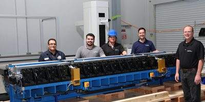
The team at LBNL performs designed and prototyped the undulators. To actually build the 32 production units required for the hard x-ray line, LBNL selected Motion Solutions, along with one other vendor.
Hard x-ray undulator design
A linear array of 259 miniature magnets is mounted along the inner edge of each strongback; the rest of the structure is designed to position the strongbacks parallel to one another with a specified gap. Each undulator rests on a girder held up by support posts; the entire assembly weighs about 6 tons.
The strong backs can be adjusted independently, which makes it possible to modify the gap while keeping the vacuum chamber housing the x-ray beam centered in the magnetic field. Each strongback rides on a recirculating roller guide, and is adjusted by two rotary motor/ball-screw actuator pairs capable of moving it at a rate of roughly 1 mm/s. An absolute optical encoder at each end of the undulator monitors the gap and prevents the introduction of a taper between the two. A third absolute optical encoder system monitors the system for tilt.
Motion Solutions performs the full integration of the undulators based on the LBNL design specifications. We receive the magnet modules, integrate them with the strongbacks, aligns them, and finishes the full assembly of the undulator.
Nonlinear spring system
Controlling the gap is essential to the performance of the entire system. When the gap is at its smallest, the magnets exert several thousand pounds of force, which falls to zero as the strongbacks are separated. To enable the electromechanical positioning system to tune the gap with micrometer-scale resolution, the LBNL team implemented a nonlinear spring-based compensation system.
Spring force normally varies linearly, while the strength of the magnetic field across the gap changes exponentially. The LBNL team designed an assembly of conical springs that can be tuned to mimic the force-distance curve of the magnetic field. Each strongback has 18 nonlinear spring assemblies across its length. The nonlinear spring system makes it possible to build a much more compact device, although the installation and calibration add to complexity. Motion Solutions assembles and tests the spring components for each undulator we build.
It’s quite a process. We measure the load deflection curve of each individual spring, then we use a sorting program to match four springs together to generate a combined curve. Next, we individually test each assembly of four springs to make sure that it matches the theoretical curve. Finally, another sorting program analyzes the data and maps the position of the individual subassemblies and identifies the proper location for each to give the desired equal force along the length of the strongback.
Collaborative efforts
The LBNL team normally takes full responsibility for the design of the undulators. For these undulators, however, Motion Solutions contributed motion control expertise.
The system was originally designed so that the motor bearings supported the ball-screw actuators. The problem was that this approach would overload the motor bearings and potentially cause premature failure. The motor bearings are not intended to be used to support the thrust load imposed by the ballscrew actuator. We suggested that they use a ballscrew support unit as a way to take the axial loads from the load screw. This design modification was adopted by the LBNL team as the official design and passed on to the other undulator vendor.
In addition, Motion Solutions verified the design parameters of the drive system, which consists of the motor, the drive screw, the motor coupling, and the drive screw nut. We also helped with the procurement of drive system components, including the precision-ground drive screws.
Maintaining tight tolerances
The magnet modules need to be aligned to the micrometer level and maintain that alignment across the full assembly of the undulator. “Each undulator is a 3.5 m device, so it’s not trivial for us to maintain those tolerances,” said Leitner. The undulators were designed with very tight mechanical tolerances for reasons that went beyond just performance. Tight specifications simplify subsequent magnetic field tuning steps. The magnet modules are designed and built so that the magnetic poles can be adjusted to the exact position. After this one-time alignment step, the magnet modules are attached to the strongbacks. Tight mechanical tolerances ensure that the magnetic field distribution will be maintained.
Tight tolerances also expedite commissioning. Even high-quality magnets have small variations and imperfections in the bulk material. Compensating for this requires the addition of magnets just a few millimeters across at various points along the magnet modules. Tuning and calibrating each undulator is a painstaking, time-consuming process that requires repeated measurements. Meanwhile, the schedule called for commissioning four undulators per month.
“We have to be able to tune and calibrate them fairly quickly, so our design is optimized to get through tuning fast,” said Leitner. “In order to achieve that, we designed it with very high mechanical tolerances. So, the position of the magnets and the strongbacks and the motors and so on and so on has to conform to very stringent tolerances beyond what’s normally done.”
Meeting tolerance while keeping to schedule required some creative engineering. The roller bearings that support the strongbacks are very sensitive to the flatness of the mounting surface. The girders are supported on each end by a pair of pads that rest on the support pillars. Two of the pads are V-supports and the fourth is a flat pad to enable the girder to be aligned very precisely to the beamline without being over constrained. Once deployed, the girders must can exhibit no more than 50 µm of sag across the 3.5 m span.
The girders are fabricated of top plates and supporting structural plates that are welded together. The length of the span coupled with the mass of the material causes sag to exceed tolerance. The initial process for fabricating the girder required a machining step to correct sag. The problem was that residual stresses from the welding caused the metal to react unpredictably during machining. As a result, the procedure for an additional hand polishing step to correct any areas that were still out of tolerance.
Our team took a different approach, starting with a special holding fixture to properly support the girder during an annealing step to release residual stresses and during subsequent machining. We came up with fixture that holds the part as it would be held during use in the undulator line. The fixture prevents the girders from deforming during the heat treatment. We were able to get the girders to meet tolerance without any additional hand working. The approach also eliminates additional inspection after the hand reworking step. The result is a faster fabrication process and a more structurally stable product.
Precision on a grand scale
Assembling the undulators and performing final testing required a computer measuring machine (CMM) capable of micron scale accuracy and repeatability. Motion Solutions evaluates the undulators and girders using a 257-inch granite CMM with an accuracy of ±10 µm and a repeatability of 2.5 µm. When the undulators ship, they are fully qualified on the mechanical level.
The LCLS-II is scheduled to go live in 2020. For now, work continues to finish the undulators and install them. To date, Motion Solutions has delivered six undulators, the first of which is fully calibrated and ready for installation.
We’re used to doing tight tolerance work on tabletop systems. The LCLS-II undulators operate on a completely different scale. We have to work to tighter tolerances than our normal systems on objects that are 10 times as large. It has been really challenging but also really rewarding.
The success of the Motion Solutions undulator work has propelled the larger LCLS-II forward toward the day it will help enhance our understanding of the world around us. At Motion Solutions, we like to talk about our mission being to make the world a better place. The LCLS-II absolutely has the potential to change the world. It has been enormously exciting and inspiring to play a part in building it.

About the Author
Wally Logan is vice president of engineering at Motion Solutions.