
Why Stepper Motors can be More Effective than Servo Motors for the right application.
Stepper motors are simple, reliable, low-cost motors that are good choices for many applications. They deliver very high torque at low speeds. They can be operated open-loop and when driven in microstepping mode, can achieve resolutions as good as 125 nm. Despite these benefits, stepper motors are often passed over in favor of servo motors because of a perceived problem – that they lose steps and don’t arrive at the commanded position. That’s incorrect. There is no such thing as lost steps in stepper-motor operation when used correctly. Once you understand the real source of the issue and how to address it, you can take advantage of these tough little motors to build some very effective systems.
First, let’s take a quick run through the basics. The stepper motor is a synchronous brushless motor with a permanent-magnet rotor and a wound stator with a very high pole count. When the stator windings are energized, they generated magnetic flux distribution that interacts with the rotor field to apply a turning force. Unlike DC motors, which operate off of continuous current, stepper motors run off of pulsed current. In full-step mode, each pulse energizes the appropriate winding pairs to advance the rotor one step (see figure).
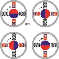
In full-step mode, each pulse of the drive current energizes windings in succession (clockwise from top left) to advance the rotor one step.
This figure shows a two-pole motor for simplicity; actual stepper motors can have pole counts of 50 pole pairs (1.8° per step), 100 pole pairs (0.9° per step), 200 pole pairs (0.45° per step) or higher. The high pole counts make the motion quasi-continuous.
Because stepper motors are driven in steps or fractions thereof, they can be operated open-loop-the drive sends a specific number of pulses and the rotor arrives at the commanded position. At least in theory, which brings us to the topic of this article.
A stepper motor can be modeled as a spring-mass system, with magnetic field acting as the spring and the rotor/load acting as the mass. Before rotation can begin, the motor needs to overcome the detent torque of the un-energized windings and the inertia of the rotor, as well as the load and any mechanical friction in the system (e.g. bearings, linear guides, ball screws, etc.). The drive can send pulses to the motor but the rotor won’t begin to move until the torque is strong enough to overcome these forces. At that point, there will be a variation between the commanded position and the actual position. That doesn’t mean that the motor has lost synchronization, however, (unless the motor is undersized for the load and stalls). The variation represents a reduction in accuracy, not a loss of synchronization. To lose synchronization, we would need to jump from one pole to the next, or 1.8° in a standard 1.8° stepper motor, which again only happens if the system is sized improperly. To explain why, we need to start with microstepping.
Microstepping
Up until now, we’ve been discussing stepper motion in the form of full steps. Stepper motors can also operate in other modes. Microstepping is a very common operating mode that uses specialized drive signals (typically, a pair of stepped sine waves 90° out of phase with one another) to subdivide each full step into tens or even hundreds of incremental units (microsteps). Microstepping offers several benefits. First, breaking each full step into a large number of smaller steps smooths the motion, reducing vibration. Second, microstepping offers a way to increase motor resolution and accuracy electronically. That said, there are implementation challenges that can result in underperforming systems.
It’s easy to get caught up in the advantages of microstepping. After all, dividing each full step of a 1.8° stepper motor into 256 microsteps gives a total of 51,200 micro steps per revolution, which is a substantial increase in resolution. The problem is that at the end of the day, we can’t escape the basic physics of our spring-mass system. The motor still needs to overcome detent torque, load inertia and friction before the rotor can move.
The amount of incremental torque tI generated per microstep decreases as
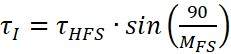
where tHFS is the holding torque per full step and MFS is the number of microsteps per full step. In other words, the smaller the size of the microsteps, the lower the ability of the drive signal to generate enough torque to make the rotor advance. What this means is that if our high-resolution microstepping motor receives a command to advance one microstep, the rotor is not likely to move. It probably won’t move when it receives a command to advance several microsteps. Depending on the system, a microstepping motor might need the accumulated torque of tens of microsteps (see equation 2) before the rotor can break friction and begin turning:
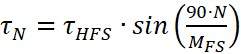
where tN is the torque generated by N microsteps At that point, it may not arrive at the commanded position or it may overshoot (although friction in the system can help damp oscillation). For a 1.8° motor microstepping with 256 microsteps per full step, commanding 100 microsteps might result in the motor shaft only turning 96 microsteps or 105 microsteps. These deviations represent positioning error¾reduced accuracy¾but the error is not large enough to cause loss of synchronization. That would only happen if the error exceeded half the full step size (in this case, ±0.9°), which would be the result of a serious design flaw and not normal operation.
How do we increase the accuracy, then? From equation 2 there are three ways to increase resolution:
- Increasing the holding torque of the motor holding torque of motor
- Increasing the number of poles and subsequently lowering the number of microsteps per full step thus keeping the resolution the same
- Decreasing the overall load or friction in the system.
So, let’s have an example. We have a ballscrew system that takes 5 oz-in of torque to overcome the friction in the system (linear guides, ballscrew stiction, etc.). If we have a motor with 100 oz-in holding torque and we use 50,000 steps per rev (250 microsteps per full step), the incremental torque per microstep is
tI = 100 oz-in × sin(90/250) = 0.63 oz-in
It would take eight microsteps before the system could overcome the static friction. What if we switch to a 0.9° motor, maintaining resolution at 50,000 counts per revolution and keeping the system otherwise unchanged? Then we have
tI = 100 oz-in × sin(90/125) = 1.26 oz-in
Now, it would only take four microsteps before the system could overcome the static friction.
Accuracy versus resolution
Misconceptions around the spring-mass model can lead to designers specifying systems that fail to perform as expected. In theory, microstepping our 1.8° motor at 256 microsteps per full step should give us a resolution of 51,200 microsteps per revolution. Stepper motors operate in the real world, though. The true mechanical resolution of the motor might only be 4000 microsteps per revolution. A heavily loaded motor in a high friction system may only achieve 1000 microsteps per rev, while a motor moving a very light load mounted on air bearings might reach 8000 microsteps per rev, but performance is always going to be limited by the physics.
Even our real-world system has limitations. Paired with a ballscrew with a 1 mm thread pitch, our 8000-microstep motor should in theory be able to achieve a linear resolution of 125 nm per microstep. In reality, we cannot use this system for nano-scale positioning. The motor won’t be able to overcome static friction and move the load until it’s been commanded to advance maybe 10 counts.
Because of the misunderstandings we’ve been discussing, many times engineering teams will just assume that a servomotor is a better solution. That’s not necessarily the case. Consider a moderate speed, horizontally oriented system like a microscope stage. This is a good application for a micro stepping stepper motor. A 1.8° motor and 10 mm ballscrew combination that achieves a resolution of 4000 microsteps per revolution can give us repeatable open-loop positioning of 2.5 µm. It wouldn’t make sense to use servo motor on that system because we would pay more without getting significantly better performance.
Stepper motors are simple, reliable, low-cost devices that can be effective on even micron-scale applications. When you understand the physics behind the system and its effects on accuracy, you can build a realistic system that can take advantage of their capabilities and save you money at the same time.

About the Author
Bill Lackey is Vice President of Automation.
Contact:
Motion Solutions
15091 Bake Pkwy
Irvine, CA 92618
(949) 586-7442
Connect with us on LinkedIn.