White Papers

How to Choose the Best Motion System for Your Step and Settle Application
Introduction
Step and settle motion plays a critical role in applications ranging from life-sciences to medical to semiconductor and materials science. In systems like DNA sequencers, diagnostic imagers, or wafer-inspection systems, stages are fundamental to the success of the product. Selecting positioning equipment for these demanding applications is a complex balance of performance versus cost. The price of a solution can range from thousands of dollars to tens of thousands of dollars, so taking the time to properly specify a system that can meet requirements is critical to making sure the end product is both effective and competitive in the market.
What is step-and-settle motion?
In step-and-settle motion, the position of a system is commanded to change incrementally (in steps), with certain processes happening at each step. Such processes include probing or imaging a DNA well, a tissue sample, or a semiconductor chip. Motion typically involves an XY stage that positions the sample of interest while a Z-axis stage is used to position the measurement head or adjust the focus of the image sensor. The motion system needs to accurately index the load to the commanded position and stabilize as rapidly as possible for the reading.
In most cases, the XY stage and the Z stage are not integrated into a single stage. The two may also have different positioning requirements. It is important to have a clear understanding of what is required of the system since the performance of one assembly may affect the technology/component choices of the other. For example, in an imaging system that uses a Z stage for autofocusing, the smaller the vertical runout of an XY stage assembly, the lower the range required of the Z stage.
Applications that require point-to-point motion depend on the step-and-settle performance of a system. The steps are not necessarily contiguous. In pathology labs, for example, technicians may wish to compare cells from different sides of a sample.
Step-and-settle performance may be important even when the stage is used for raster scanning. For example, in raster scanning, the system may capture a sequence of exposures that are tiled together to create a single image. The motion systems need to be highly accurate and repeatable to create a proper mosaic. Raster-scan imaging is frequently automated for high-throughput processes such as semiconductor wafer mapping. The speed required from the motion system depends on resolution—lower-resolution images may not require high-speed motion.
Motion systems for step and settle
There are several motion architectures for achieving this task. Let’s look at the pros and cons of each:
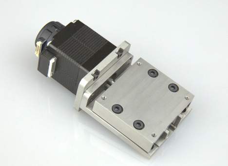
Open-loop stepper-driven lead-screw stages
Stepper-driven lead-screw stages can deliver sub-micron resolutions in a compact, economical package. They have positioning repeatability on the order of a few micrometers. With proper screw pitch, lead-screw stages can be self-locking in vertical orientations. They offer the lowest speeds of the different classes of drive systems but are effective for raster scanning with the right application. They are frequently used for medical diagnostics such as automated histology systems.
Stepper-driven lead-screw stages with rotary encoders
These devices deliver many of the benefits of their open-loop cousins. The addition of closed-loop feedback increases performance, enabling them to reach resolutions as good as 50 nm to 100 nm with effective tuning. On the downside, the addition of feedback increases in-position jitter. Repeatability improves, but not to the sub-micrometer level.
Linear-motor stages with encoders
Linear-motor stages are direct-drive stages for applications requiring fast motion and good positioning repeatability. They are easily customized and when they incorporate ironless motors, provide exceptionally smooth motion. They cannot maintain position in the power-off condition. As a result, vertically oriented stages will need an external brake or a load-biased counterbalance. Linear-motor stages are good for high-speed applications like genomics. With proper encoder choice, they can achieve sub-micron repeatability and resolutions as good as ±5-10 nm.
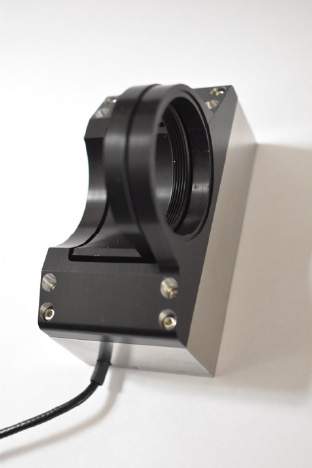
Voice-coil actuators with linear encoders
A voice-coil motor is a specialized linear motor based on a single-phase DC design. Voice-coil motors have higher resonant frequencies than conventional linear motors. They provide only limited displacement but are very fast, making them suitable for high-speed applications. They also offer great resolution and positioning repeatability when used with an appropriate encoder. Like other linear motors, they can’t hold position in a power-off condition so if they are used for Z focus, they require an external brake or some form of load bias.
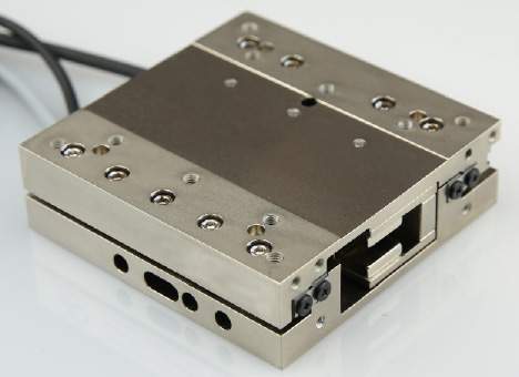
Piezoelectric actuators with feedback
Piezoelectric actuators provide ultrahigh resolution and repeatable positioning, in the single to tens of nanometers range. These devices are frictionless and do not generate heat. They are highly tunable and easily customizable. On the downside, their range of travel is limited. They are mechanically stiff but do not hold exact position in a power-off state. Sweet-spot applications include mask alignment, wafer inspection, and autofocusing.
Hybrid piezo/stepper stage with linear encoder
This hybrid stage combines a piezoelectric actuator for short, high-resolution moves with a screw-type stage for longer distances. The combination provides extremely high resolution (a few nanometers) and repeatable motion over long ranges (50 mm or more). Hybrid stages are both highly robust and easy to tune. Because lead-screw actuators can be self-locking, a hybrid stage can be designed to hold position in the power-off state. On the downside, these types of stages operate at slower speeds than linear-motor actuators, for example. Hybrid stages are ideal for applications requiring high precision positioning and ultra-fine alignment.
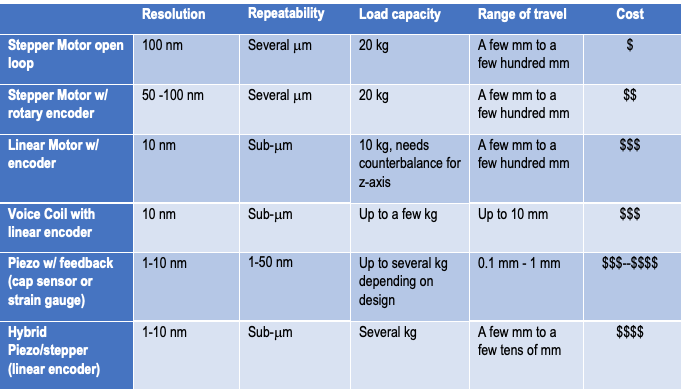
Table 1: Summary of actuators used for step and settle
Parameters for specifying step-and-settle motion systems
Travel range
Travel range is the maximum travel that is required during the step-and-settle motion. Just specifying the distance the stage needs to travel for the actual readings is not enough. Often, a stage needs to travel a longer distance, for example to move out of the way while a sample is being exchanged. It’s essential to know both travel ranges in order to understand if a single stage solution is adequate or a stacked mechanism will be necessary.
Resolution
This is the minimum step size that the stage is required to reliably perform. Resolution can be dictated by the depth of focus in an autofocus application or the pixel resolution that an indexing application may require. In general, resolution is directly proportional to price (the higher the resolution, the higher the cost).
Settling time
This is the time required for a stage to move a specific distance and settle within a specific position tolerance. The settling time is highly dependent on system bandwidth. System bandwidth is a function of the stage resonance and the capabilities of the drive, measured in hertz. Knowing the system bandwidth tells us how well something can be controlled. It is typically defined for closed-loop systems and is also highly depended on the control parameters that the user selects.
For step-and-settle applications, it’s essential to specify:
- How fast the stage should be able to complete a move
- How it should perform at the end of a move
- What constitutes the end of a move
This information describes the behavior of the stage at the point when an action is being taken, such as capturing an image. For example, the specification might call for a stage that is capable of:
- completing a 0.1 µm move with less than 30% overshoot
- settling to within ±7 nm of commanded position within 3 ms of starting the move
- maintaining stability for 35 ms, until the next move.
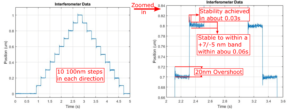
Once the appropriate stage has been selected, it is necessary to characterize its performance to determine whether it meets the requirements. This can be done by exercising the stage over a fixed number of steps in both directions. The results are presented in a “step ladder” plot of distance versus time (see Figure 1).
In-position error band
This is the maximum position error that is acceptable for calling a step-and-settle move complete. It varies by application. In-position error band is typically given as a number that is then used to define settling time.
Error band often appears on data sheets as part of the specification for settling time. It’s important to note that while error band is given as a number for the whole stage, it can vary throughout the motion of the stage as a function of vertical and horizontal runout. Improper mounting or uneven surfaces can likewise create problems. These factors should be taken into account when determining whether the settling time of a stage will be sufficient for an application.
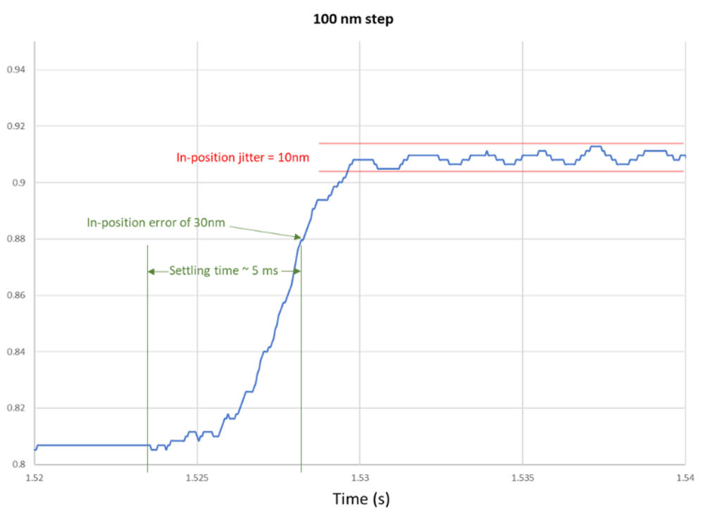
In-position jitter
This is defined as unwanted motion about a position that is present when no motion command is being executed (see Figure 2). It is also Depicted on the right-hand side of Figure 1. In-position jitter can appear after a move is complete, or it can introduce noise such that the move never completes. If a motion system works in the lab but not when integrated into the production system, in-position jitter is a good error source to consider.
In-position jitter is composed of three components: mechanical jitter, feedback jitter, and electronic jitter:
- Mechanical jitter: Instabilities of the mechanical system, such as resonances, can introduce jitter around the commanded location. Systems with high resonant frequencies tend to have lower mechanical jitter (more on resonance below).
- Feedback jitter: Electrical jitter from the encoder signal or jitter resulting from the system hunting for the commanded location can cause instabilities. Feedback jitter is highly dependent on the resolution of the sensor—encoder resolution that is smaller than the mechanical capabilities of the positioner can sometimes result in greater instability as the system hunts—and on the control parameters (PID gains)
- Drive electronics: The drive electronics that are working to stabilize load at the commanded position also introduce electrical jitter.
Systems can be tuned to minimize in-position jitter, but it is impossible to entirely eliminate—it’s inherent to all motion systems. Screw-driven systems tend to have low in-position jitter since they are predominantly driven by stepper motors and generally operated open-loop.
Dwell Time
This is the time between the end of one move and the start of the next. The inverse of dwell time is the stepping frequency. Repetitive incremental motion always presents the risk of exciting resonances in the system, which we will discuss below.
Accuracy and Repeatability
Repeatability quantifies the ability of a stage to reach a position repeatedly, with all variables except time left unchanged. Accuracy refers to the ability of a stage to position the load to a commanded location within some specified tolerance. When selecting stages for step-and-settle applications, it’s essential to establish the repeatability requirement early on. Accuracy can always be achieved with mapping. Repeatability varies by stage and feedback type, so be sure to determine that specification in advance.
Not all stages will achieve the same level of repeatability in both directions. Be sure to determine whether the application requires uni-directional repeatability or bi-directional repeatability and choose a compatible stage. Other factors affecting repeatability in linear stages include open-loop vs closed-loop operation, backlash, hysteresis, and encoder resolution.
Load
The shape and weight of the load on a stage is important as it will affect the resonance of the stage and its dynamic behavior in general. This includes stacked stages, which can affect one another. Off-axis loads apply a moment load that can introduce error and impact the accuracy of a measurement or the quality of an image.
For most standard objectives, load will not be a major concern, but for custom optics or for positioning cameras etc. with a Z-focus stage, load and load bias can be major issues. Load is straightforward and can often be mitigated by decoupling the focus from other parts of the system.
Load bias refers to the behavior of a stage upon removal of power. This is a particular concern for Z-axis stages and can be critical in applications in which damage to valuable samples or optics can occur.
- Piezo stages: In the power-off condition, a piezo stage will translate the load to an indeterminate point near the center of travel.
- Linear motors and voice coils: These motors do not have any holding torque in the power off condition. If they are vertically oriented, the load will fall to the lowest end-stop position. Many of these systems already include counterbalances. The way to create a safe power off condition is to give the counterbalance an upward bias such that loss of power results in a net upward force.Note that linear motor and voice-coil systems are designed, tuned, and counterbalanced for a specific load. Changing loads by more than 10% can lead to performance degradation or instability in the system.
- Screw-type actuators: When using ball screws (which are 90% efficient), the load will descend to its lowest point when powered off. A power-off motor brake can mitigate this behavior but increases cost and size of the stage. A standard lead screw is the only self-locking option that will inherently not move after a loss of power.
Factors impacting system performance
Flatness and straightness
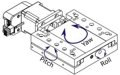
All linear guides have some intrinsic out-of-plane motion that is introduced along all three axes: roll (rotation around the X axis), pitch (rotation around the Y axis), and yaw (rotation around the Z-axis; see Figure 3). Pitch corresponds to the flatness of motion (vertical run out), while yaw corresponds to straightness of motion (horizontal runout). Given the interdependencies of step-and-settle motion systems, it’s important to control roll, pitch, and yaw.
For an example, consider an automated tissue imaging system that uses a raster-scan step-and-settle process. The XY stage translates the sample underneath the imaging objective, while the Z-axis positioner handles autofocus. When using a stage to adjust focus, it is critical that the objective remain in-plane with the sample. If the XY stage has too much vertical run out—lack of flatness—the autofocus system may be unable to compensate. Horizontal runout—lack of straightness—has a different effect. It introduces positioning error that can interfere with the system’s ability to tile exposures to create a full image.
Horizontal and vertical runout can vary over the distance of travel. This is unlikely to be a problem if the distance is matter of a few millimeters but if the range of travel is 75 mm, it could have an impact. It’s important to ensure that the stage will perform as required at all positions. Mounting can have an effect on runout, as well, so OEMs should follow best practices to avoid introducing stresses.
The choice of bearing and preload can be used to optimize flatness and straightness. To make sure we are providing stages that maintain excellent straightness and flatness, Motion Solutions uses only crossed-roller bearings and flexures in our focus stages. This approach produces stages with out-of-plane motion that can be measured in thousandths of a degree.
The mechanics that convert motor torque into linear motion play a significant role in generating pitch and yaw. In linear motor, piezo, or voice-coil stages, force is applied purely in the direction of motion. Our designs ensure that the position of the force minimizes parasitic motion due to force imbalance. However, in screw-driven stages, screw eccentricity and friction between the screw and nut can cause force on the system that is not in the direction of motion. Motion Solutions has developed a drive system to mitigate this source of out-of-plane motion. Key features include directly coupling the screw to the rotor of the motor and the use of a proprietary interface between the nut and the load. This drive system, combined with stiff crossed-roller bearings, equips our screw-driven stages to serve applications that previously required more expensive voice-coil and linear-motor systems.
Resonance
Every mechanical system has some intrinsic resonance that can be excited by motion. Because high-speed motion or high-frequency steps excite resonances, this effect has implications for the operation of a stage. Crossed-roller bearings, for example, ring at 20 Hz, so step-and-settle motion with 50-ms dwell times can be a problem. At the other end of the scale, ultrahigh-frequency stepping can likewise cause issues.
Techniques exist to mitigate the problem. Filtering the drive signal—for example, using a notch filter to avoid exciting bearing resonances—can be very effective. This technique will allow the stage to be driven harder before motion becomes unpredictable. To support ultrahigh-frequency operation, a stage may need to be designed with special mechanics. Bear in mind that every stage has a top speed beyond which it can no longer be reliably controlled, so choose the motion system appropriately.
Conclusion
Z-focus and scanning stages power a host of essential applications. To find the optimal solution for your project, use the list above to establish a general specification. Review the motion technologies available to find the best fit. As in all engineering, choosing a stage will involve trade-offs. Know your priorities going in, whether that’s performance, budget, size, or even lead time. Particularly for demanding applications, selecting and implementing a stage can be complex. Take advantage of the expertise of your vendor to identify the best solution. Most important, start the design of your motion system right from the beginning of product development. Work with a vendor who has the know-how and capital equipment to help you make data-driven decisions about your step-and-settle application—you’ll be happy you did.
Motion Solutions has a broad range of stages for step-and-settle motion, including proprietary design. To find out how our motion experts can help with your latest design, contact us.
Categories
- Case Studies
- Company News
- Customer Focus
- Engineering Insights
- Featured Products
- Industry Perspectives
- nPoint Blog
- Our Take
- Product Spotlight
- Uncategorized