
[Editor’s note: For a detailed discussion of how to specify the stage for step and settle applications, see our whitepaper https://www.motionsolutions.com/white-papers/how-to-choose-the-best-motion-system-for-your-step-and-settle-application/
Step and settle motion is a fundamental support technology for a variety of critical systems, such as DNA sequencers, semiconductor wafer-inspection systems, diagnostic imagers, and more. While OEMs typically focus on their core value propositions, they need to properly specify the motion stages if the product is going to succeed. That process is trickier than it sounds. Designers need to find a complex balance between performance and cost while avoiding a number of pitfalls. Here, we offer five tips to help you optimize your next project.
Tip #1: The XY stage and the Z stage are distinct but interrelated
You might be using stages to position a load in 3D space but the performance requirements of the XY stage will probably be different from those for the Z stage. At the same time, there are interdependencies at the system level, even if the stages are not physically connected. For example, reducing the vertical runout of the XY stage makes it possible to use a Z stage with a shorter range and thus, lower cost and potentially higher bandwidth.
Because the requirements for XY positioning are often different than for Z focus, make sure to match the stage technology to specifications. The variety of choices available simplifies the balance between performance and budget (see table).
| Resolution | Repeatability | Load Capacity | Range of Travel | Cost | |
|---|---|---|---|---|---|
| Stepper Motor open loop | 100 nm | Several µm | 20 kg | A few mm to a few hundred mm | $ |
| Stepper Motor w/rotary encoder | 50 -100 nm | Several µm | 20 kg | A few mm to a few hundred mm | $$ |
| Linear Motor w/encoder | 10 nm | Sub-µm | 10 kg, needs counterbalance for z-axis | A few mm to a few hundred mm | $$$ |
| Voice Coil with linear encoder | 10 nm | Sub-µm | Up to a few kg | Up to 10 mm | $$$ |
| Piezo w/feedback (cap sensor or strain gauge) | 1-10 nm | 1-50 nm | Up to several kg depending on design | 0.1 mm – 1 mm | $$$–$$$$ |
| Hybrid Piezo/stepper (linear encoder) | 1-10 nm | Sub-mm | Several kg | A few mm to a few tens of mm | $$$$ |
Tip #2: Define operation before calculating accuracy and repeatability
Before you try to specify accuracy and repeatability, focus on clearly defining the performance required by the application. Questions to answer include:
- How fast should the stage be able to complete a move?
- How should it perform at the end of a move?
- What constitutes the end of a move?
Success lies partly in the amount of detail given in the responses. For example, an application might require a stage capable of:
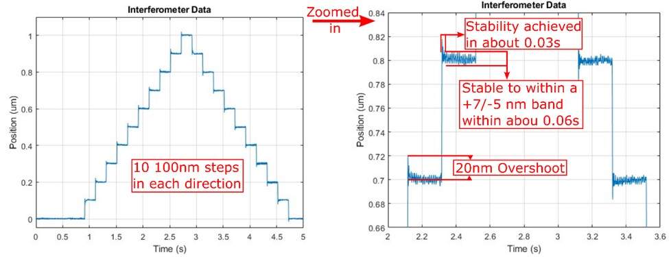
- Finishing a 0.1 µm move with an overshoot of under 30%
- Settling to within ±7 nm of commanded position within 3 ms of starting the move
- Maintaining stability for 35 ms, until the next move
This kind of detail lets us calculate top line performance metrics and select a stage that can do the job. Speaking of which…
Tip #3: Characterize the stage to make sure it meets requirements
Don’t take data sheet numbers on faith. Ask to see a “stepladder” plot with data captured under application conditions to make sure the stage can do the job. A stepladder plot is generated by exercising the stage a fixed number of steps in each direction, then plotting position as a function of time (see Figure 1).
Tip #4: Ask how in-position error band is defined
In-position error band is used to determine settling time for a stage. Many data sheets list it as a single number. It’s important to remember that stage performance varies across the length of travel as a result of intrinsic vertical and horizontal runout, often worsened by issues like improper mounting or uneven surfaces. Make sure that the stage can operate with the required in-position error band/settling time throughout the range of interest and not just at a single position.
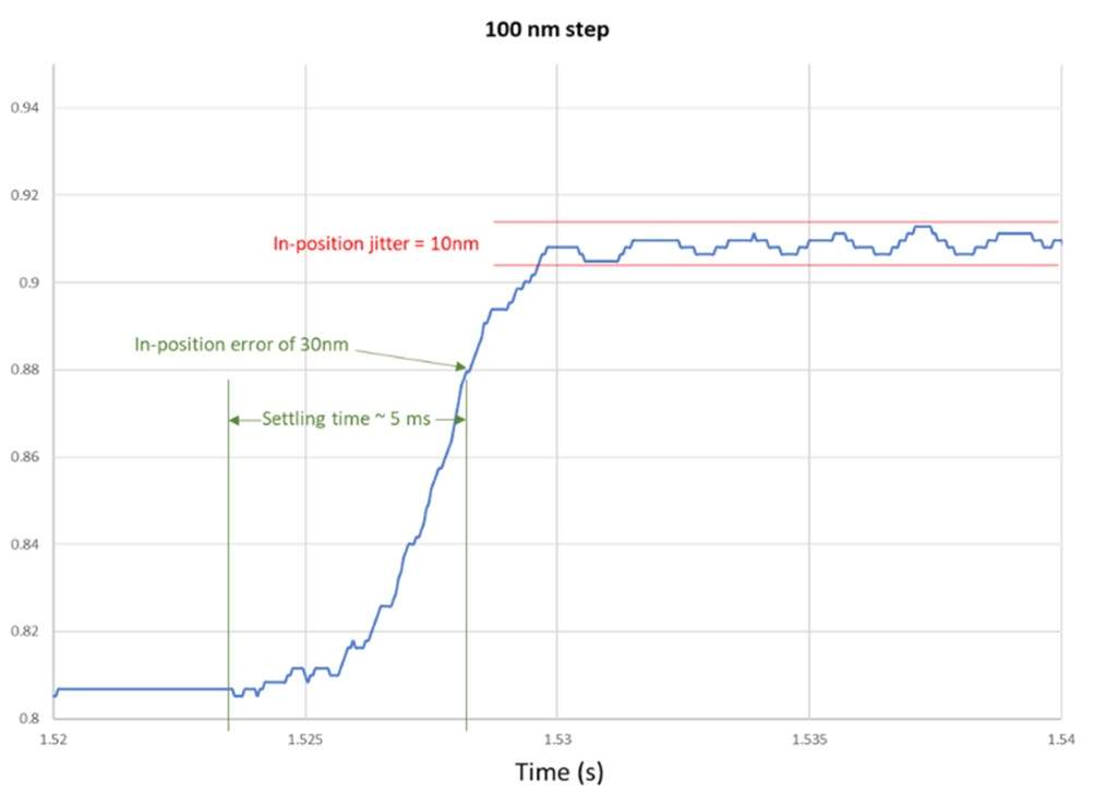
Tip #5: Don’t forget In-position jitter
The fuzziness shown on the horizontal segments of Figure 1 is jitter, representing unintended movement in the absence of a motion command (see Figure 2). It can be caused by mechanical instabilities, feedback, or drive electronics. In-position jitter can appear after the completion of a move or it can be caused by behavior that prevents the move from completing it all. If your motion system works in the lab but not when deployed, consider in-position jitter as a possible cause.
Conclusion
Choosing and implementing a stage for a step and settle application can be challenging. Make sure that you fully characterize the needs of your application. Pay attention to the points raised above. Consider the design of your motion system from the beginning of product development. Perhaps most important, work with a vendor who has the know-how and capital equipment to help you make data-driven decisions about your step-and-settle application—you’ll be happy you did.
Motion Solutions has developed step and settle motion systems for hundreds of projects using off-the-shelf, customized, and proprietary components. To find out how our motion experts can help with your latest design, contact us at [email protected].
About the Author
Matt Luxton, Product Specialist for Precision Motion