White Papers
A Cost-Conscious Approach to Boosting Accuracy in Screw-Driven Stages
Introduction
One of the most important aspects of engineering is choosing the most effective solution for the task at hand. That means finding a balance among factors like accuracy, footprint, and cost. Linear-motor stages might provide the best performance but are frequently too expensive for many applications. Screw-driven stages are economical but small errors in the screw introduce a cyclical error that can reduce flatness and straightness to unacceptable levels. One approach to improving the performance of screw-driven stages is to control other sources of flatness and straightness errors by increasing stage stiffness with cross-roller bearings. The problem is that cross-roller bearings introduce trade-offs of their own, increasing cost and footprint. For cost-conscious applications, we offer a third option – damping cyclical screw error with a specialty carriage-to-nut coupling. It’s an economical approach that can significantly enhance the performance of a mid-level stage without breaking the budget.
Cyclical screw errors
Screw actuators convert rotational motion into linear force using a nut attached to a helical screw. As the screw turns, the nut and attached carriage/load travel linearly. In an ideal world, that thrust will be straight, without deviation (see Figure 1).

Unfortunately, these helical screws are machined devices, and whether they are rolled or precision ground, there is always some degree of error in helix angle over each 360° of rotation. These errors, in turn, lead to over travel and under travel. In addition, eccentricities and other types of distortion in the screw shaft introduce parasitic motion in the form of cyclical roll, pitch, and yaw.
We can break positioning error into two components: systematic error, caused by error in the helix angle and cyclical error, caused by eccentricity in the screw shaft. (Note: there are also intermediate travel errors, but they are outside the scope of this discussion.)
- Systematic error: average error per 300 mm of travel
- Cyclical error: error introduced in each rotation by eccentricity
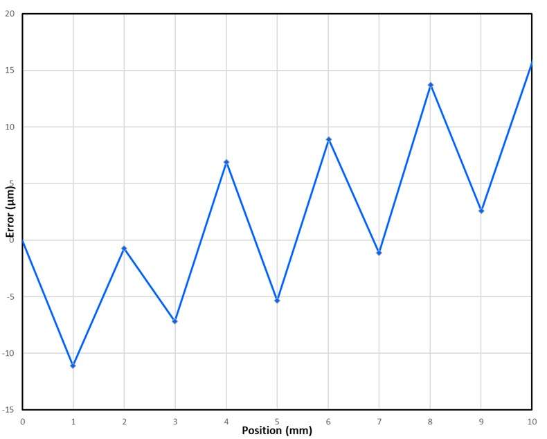
Systematic error is consistent. It’s easy to measure and can be compensated for in the control loop via an offset table. Cyclical error introduces an error in the motion of the nut – and the carriage – that can’t be averaged out. It reduces the flatness, straightness, accuracy, and repeatability of the stage (see Figure 2). The motion of the screw is amplified by the lever between the nut and the bearings. Even if the shaft errors are on the order of microns, they can still significantly impact applications with micron or even submicron accuracy and repeatability requirements.
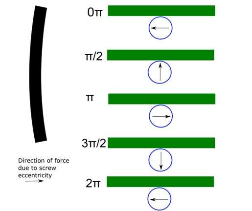
The shaft distortion shown in Figure 2 is well behaved but that is not necessarily always the case (see Figure 3). Also, because eccentricity and distortion can vary over the length of the shaft, measuring cyclical screw error can be difficult and time-consuming, making it challenging to correct with software.
One solution is to upgrade the mechanics of the stage, for example using cross-roller bearings. Cross-roller bearings increase stiffness to maximize the flatness and straightness of the stage, minimizing the effect of cyclical screw error. The trade-off is that cross-roller bearings are significantly more expensive and require expertise for effective use. Perhaps more important, a cross-roller bearing has to be roughly twice as long as the desired distance of travel, which may be unacceptable for space-constrained applications.
That’s the bad news. The good news is that there is a straightforward mechanical solution that can significantly reduce the effects of cyclical screw error, enabling screw-driven stages to deliver performance suitable for many precision applications.
The secret’s in the coupling
Cyclical screw error is transferred from the screw to the load via the nut that connects the carriage to the screw. We can’t eliminate machining imperfections and it’s not feasible to correct the issue through software. Given that the error is mechanical, it follows that we ought to be able to find a mechanical solution.
At Motion Solutions, we have developed a drive system that combines couples the screw directly to the rotor of the motor to eliminate backlash. It also couples the nut to the carriage in such a way as to absorb out-of-plane motion while remaining rigid in the direction of travel. Instead of having to invest in a linear-motor stage or expensive upgrades to a screw-driven stage, it’s possible to just change the coupling and get a substantial performance enhancement for minimal investment.
We demonstrate the technology using our LGS25 screw-driven linear stage. These midrange linear actuators offer up to 1 m of travel with a choice of lead screw or recirculating ball screw. In their stock configuration, LGS25 stages are good off-the-shelf solutions for budget-conscious applications with moderate performance requirements. With the addition of our flexure-based coupler, performance improves (see Figure 3).
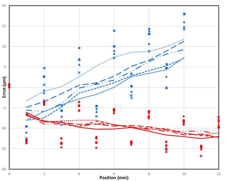
We compared the results of five data runs taken for the LGS stage with the standard nut (blue) and the flexure-based design (red). The lines show moving averages of the data set (see Figure 4). Note that the flexure-based stage has significantly better repeatability and reduced run out over the length of travel.
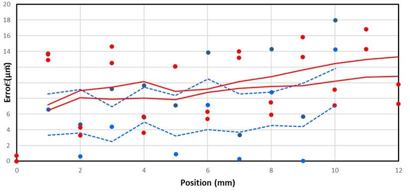
Plotting the absolute value of the maximum and minimum errors for the standard nut stage (blue) and the flexure-based stage (red) provides another view of decreased error and increase repeatability (see Figure 5). Note, in the case of these two stages, the flexure-based version displays a fixed micron steady-state error that is greater than that of the standard-nut stage. Because the flexure-based stage has such high repeatability, however, this steady-state error can be addressed by applying an offset in the control loop. The result is highly accurate performance from a modestly priced stage.
Conclusion
There was a time OEMs choosing linear actuators faced a significant cost jump from low-end screw-driven stages to cross-roller bearing screw-driven stages to linear-motor stages. The flexure coupling fills a gap in the progression, giving OEMs with cost-sensitive designs a budget-friendly path to higher performance.
Reducing cost while maintaining quality requires insightful engineering. At Motion Solutions, we leverage our experience in design and manufacturing every day to help customers stay within budget while achieving the performance they need. For applications that require ultrahigh speed and repeatability, there is still no replacement for a linear-motor stage. But by solving the problem of cyclical screw error, we’ve developed a method to upgrade the performance of more economical screw-driven stages to serve applications requiring high performance on a budget.
Find out how the LGS25 screw-driven linear stage can give your next project high-performance motion at a budget price. Contact your Motion Solutions representative today.
Further Reading
What can cross roller guides do for you?
Understanding the Benefits – and Limitations – of Stage Error Mapping
About the Author
Matt Luxton | Product Specialist
Categories
- Case Studies
- Company News
- Customer Focus
- Engineering Insights
- Featured Products
- Industry Perspectives
- nPoint Blog
- Our Take
- Product Spotlight
- Uncategorized